


Contour measurement – away from classic methods
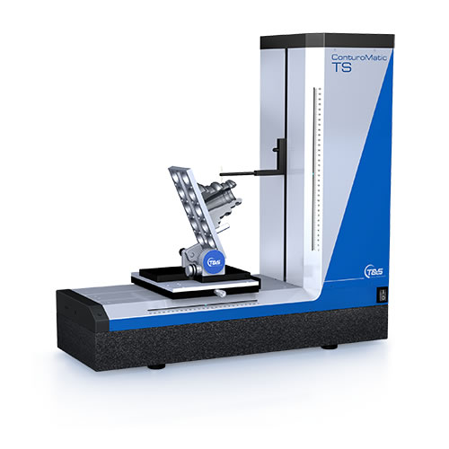
ConturoMatic TS –
simply overcoming boundaries
The connection between the X and Z measuring axes in a drive unit always leads to narrow tolerances.

ConturoMatic TS
Our solution:
separating X and Z
The feed axis assumes the function of tool receptacle while the Z-axis just performs the scanning movement. Since both axes are motorised, this leads to enormous benefits.
Both axes are controlled to keep the measurement speed constant irrespective of the contour incline. Classic combined drive units only move at constant speeds along X, which invariably leads to increased measuring point distances along steep contour sections.
This irregularity in data point equality always leads to mathematical problems that can only be solved with interpolation (algorithmically generating interim values).
Our solution automatically leads to more consistent data point distances.
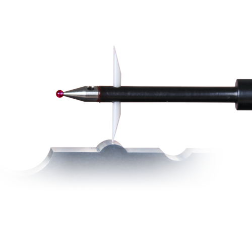
Calculation of results therefore always takes place using real, physically recorded, measured values. Furthermore, the Z-movement of a straight line is guided, meaning there is no limitation of the measuring path any more, as is caused by the circular motion of the tracing arm of conventional drive units. Our tracing arm is almost always set horizontally. The probe tip can follow the contour dynamically throughout the measuring range of up to 250 x 320 mm, and the scanning conditions are clearly defined within the entire measuring range.
Since the probe tip position is precisely defined and repeatable to within a fraction of a millimetre, secure and automatic measurement is possible even in the smallest of bores.
Additionally, guide deviations of the Z-axis, which commonly result in measuring errors due to the lever effect of the tracing arm length, are automatically compensated for by our concept.
ConturoMatic TS
More than the total sum of ideas:
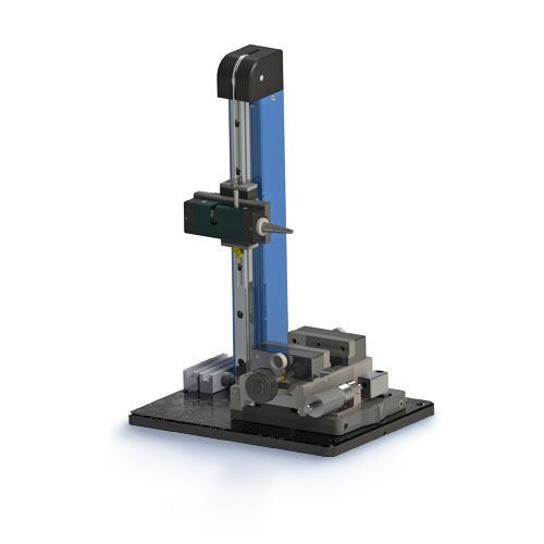
The concept behind all of the ConturoMatic TS systems mainly comprises two motorised measuring axes. The X-axis carries the sample and the Z-axis scans the contours. Both measured value recording and control are strictly based on state-of-the-art digital technology. The mechanical base is high-quality granite.
Effect:
Due to the use of precision parts within our systems, there is no need for expensive and overly complicated error correction. Stability and longevity are basic elements of our ConturoMatic products. New, different, innovative and technically revolutionary.
The technical innovations that make our new TS system the best device in its class include the integrated, maintenance-free electromechanical system for tracing force adjustment. Using this function, the tracing force can be adjusted for the contour and roughness modes of each tracing arm. These settings are set individually for each tracing arm, managed by the software and automatically adjusted according to the required measurement function. To calibrate the tracing arm and the offset between the upper and lower probe tip, only the ball standard, which is included in the scope of supply, is required.
Due to the geometrically precise horizontal position of the tracing arm, it is possible to check contours and bores with a diameter of less than 2 mm to more than 300 mm. Breakage of the probe tip is minimised by the integrated safety shutdown of the Z-axis movement. The roughness analysis option, which is activated through the integrated measuring force setting, can be used in combination with the contour analysis. In many cases, this makes further measuring superfluous. Contour and roughness results can be effectively determined in a single step. Other tasks that can be performed by our ConturoMatic-TS include the analysis of bores, distances from inner to outer contours, taper angle and parallelism, profile defects and the measurement of discontinuous surfaces, with no loss of reference measurement.

Scanning direction of the ConturoMatic TS-UD
Are your needs growing? ConturoMatic TS accompanies you in your development.
The modular concept allows cost-effective entry to the TS class with the option of retrofitting additional functions at any time. No mechanical intervention in the existing system is required; simply software activation.
Technical highlights of the TS:
- Robust mechanical base
- Large measuring range: 250 x 320
- Guiding elements from granite for the highest degree of levelness
- Integrated Y-adjustment table
- Motorised measuring axes
- Permanent dynamic speed control
- Constant data point distance irrespective of the profile declination
- Non-contact incremental linear scales. Our scales are like steel when it comes to thermal behaviour. Therefore, temperature compensation or extensive climate control are not necessary in most cases.
- Built-in control electronics
- Data recording and control via standard interfaces ensure future usability and independence, regardless of changing computer hardware
- ConturoMatic TS accuracy: ± (0.9 + L/100) µm [L = measuring length in mm]
Extension options
The extension packages, available on an optional basis, contain all the necessary components, such as tracing arms for upwards/downwards scanning, a roughness software option with roughness sensor including diamond tip, motorised Y-table for automatic zenith search, etc.
Option UD (Up/Down)
This option enables the scanning direction to be switched with no loss of reference measurement, e.g. to define bores or references from outer to inner contours.
This function is also available in combination with roughness analysis and can be integrated into automated measurement sequences.
Scanning direction ConturoMatic TS-UD
Option R (Roughness)
The roughness (R) option makes it possible to measure the surface roughness by means of reference surface measurement. Measuring contours and roughness can be combined and automated via the multi-contour function.
This function is also available in combination with the UD option.

Option Roughness
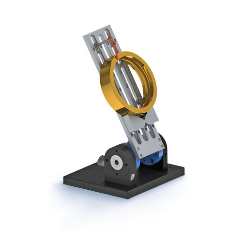
Option M (motorised Y-Table)
Software-controlled, motorised adjustable Y-table for automatic zenith search. The hysteresis of the Y-table guidance system is practically negligible and thus does not have any relevant influence on the diameter measurement or UD function. The zenith search can be carried out via the software or manually.

Option motorised Y-Table
ConturoMatic Rauheit
Contour and roughness in one step
State-of-the-art contour measuring systems enable roughness parameters to be recorded and calculated to an increasing extent. Roughness measuring of steeply inclined contours brings more and more of the previous scanning procedures and assessment methods to their limits.
To solve this problem, our calculation algorithms have been based on orthogonal regression from the outset. This method, in connection with dynamic speed control, which ensures even data point distance, leads to perfectly precise results – even on heavily tilted surfaces. In contrast, conventional solutions for achieving constant measuring point distances require the generation of theoretical points, which haven’t actually been measured, via interpolation.
With our optional surface roughness software update for the ConturoMatic TS, your contour measuring system turns into a particularly high-performance system for surface measurement.
All common parameters can be measured and evaluated automatically. The software is seamlessly integrated into the standard software and can be operated intuitively. It is also possible to update every T1 and TS system delivered to date. The update comprises software for surface roughness, a roughness tracing arm with 2 µm tip radius and 60° angle, as well as comprehensive operating instructions. The roughness option is standard for the ConturoMatic TS-X.
Standards applied to the measurement of surface indices by the ConturoMatic systems:
-
DIN EN ISO 4287:2010-07
-
DIN EN ISO 4288:1998-04
-
EN ISO 16610-21:2013-06
-
DIN EN ISO 13565-1:1998-04
-
DIN EN ISO 13565-2:1998-04
-
DIN EN 10049:2014-03
-
VDA 2006:2003-07
-
VDA 2007:2007-02 (optional)
-
ISO/TS 16610-31:2010 (optional)
Assessable indices:
- Pt, Pz, Pa, Pc, Pq, Pp, Pv, Psk, Pku, PSm, Pdq, Pmr(c)
- Rt, Rz, Rzi, Rz1max, Ra, Rc, Rq, Rp, Rv, Rsk, Rku, RSm, Rdq, Rmr(c), Rk, Rpk, Rvk, Mr1, Mr2, Rmax, R3z, RPc
- Wt, Wz, Wa, Wc, Wq, Wp, Wv, Wsk, Wku, WSm, Wdq, Wmr(c)
- Dominante Welligkeit WDSm, WDc, WDt nach VDA 2007:2007-02 (Optional)
- Filterung durch phasenkorrekte Gauß Filter
- Robuster Gauß Filter nach ISO/TS 16610-31:2010 (Optional)

Visualisation of results


Technical specifications
